Project specification is an important set of documents which is provided by the architect or building designer.
If all the information relating to a project was shown on the drawings, they would be very difficult to read. The specification provides supplementary information to the drawings, and takes precedence over any notations on the drawings.
Typically the sections included in a project specification are:
-
a description of the job, the site, the proprietor and any other parties in the contract arrangement
-
a trades section detailing standards and quality of work. This may be set by the Australian Standards or by samples constructed for the architect's approval
-
the schedules containing detailed information in tabular form on
-
windows, showing frame material and type of glass
-
doors, specifying size, material and the swing on the door
-
finishes to walls, floors and ceilings
-
door types and models of locks, latches, hinges, push plates and pull handles
-
other project specific and relevant documents.
Let's explore a few key components of the project documentation set:
1. Plan of subdivision
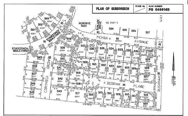
(above: example only. Subdivision plans can often be obtained from local council planning departments)
Plans come in different formats to cover different purposes.
The plan of the subdivision is prepared for planning approval prior to the development of the land. It is a good source of information relating to adjoining properties.
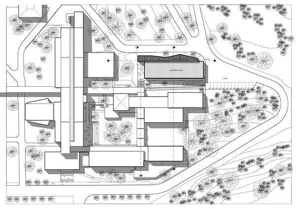
2. Site plan
(above: example only. A typical site plan containes a lot more detailed information)
The site plan shows a 'bird's eye view' of the building site showing the location of the structure on the block of land.
A good site plan can minimise the risk of building on the wrong block of land. It is usually drawn to a smaller scale than a floor plan. A 1:500 scale is generally adequate. Because the roof line is shown, the downpipe locations and stormwater drainage system can also be indicated. Setback distances from the front and side boundaries are also shown.
3. Floor plan
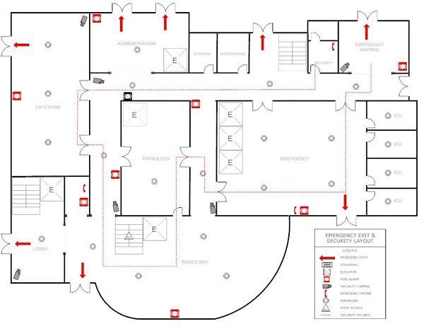
(above: example only - emergency exit plan indicating path of egress and signage)
Floor plans are like cross sections which are taken horizontally half way up the wall. They are typically
drawn to a scale of 1:100 or 1:50 depending on the type of project.
Floor plans show a vast amount of detail including:
• all horizontal dimensions such as room size and wall thickness
• size and location of windows and doors
• location of fixtures and fittings
• any particular requirements in a room such as floor coverings
• an indication of the materials used for wall construction
• the overall floor areas.
4. Cross sections
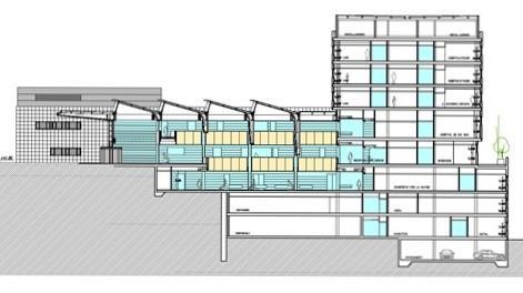
(above: example only)
Cross sections are a slice taken vertically through a given point along the building. They are generally drawn to a bigger scale than floor plans and elevations so that more detail can be shown. Cross sections indicate the type of structural materials that are incorporated into the construction.
5. Footing plan
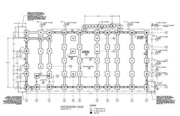
(above: example only)
Footing designs for residential projects are made to comply with AS 2879 - 2006 Residential slab and footing - construction. Dimensions are not generally shown on the footing design, so they must be read with the architectural plans.
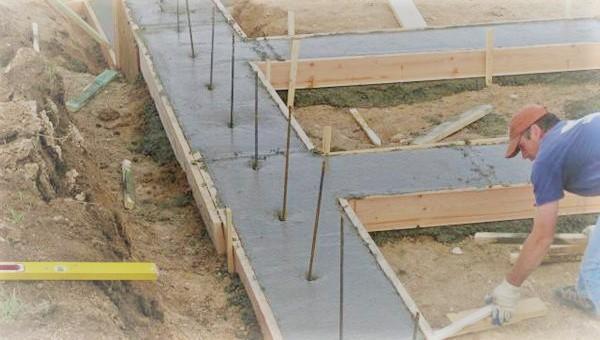
Footing plans provide details on footing depths and widths, slabs and stiffening beams and the type and positioning of steel reinforcement. These documents must also be included in a building permit application.
6. Drainage plan

(and othe functional and environmental plans)
Municipal drainage plans provide details of legal points of discharge for stormwater drainage. They may
also provide surface levels of a subdivision. Water authority documentation such as a sewer plan provides details of plumbing fixtures, drainage lines and points of attachment to existing building(s) on a site.
7. Contour plan
Contour plans are a graphical representation of the lay of the land. They show the degree of slope on a site. They typically relate back to a site datum referred to as a TBM (temporary benchmark) and may also relate to AHD (Australian height datum). They can be used to determine the extent of cut and fill needed, the height of retaining walls, and the overall finished height of buildings referenced back to natural ground level.
To produce a contour plan a surveyor takes a series of levels over the site at regular grid spacing. These readings are recorded in a surveyor's log book and converted to RLs (reduced levels), which are plotted onto a grid overlaid on the site plan. A draftsperson can then draw lines of best fit between equal RLs.
This gives lines that represent each contour interval, eg RL 5.500. Any feature matching this contour will have a level of RL 5.5 m.
8. Condition report
Prior to construction, the condition report, soil report and engineer's drawings will need to be prepared as they contain:
- information on the existing site such as the location of services
- instructions for building complex structures
- an assessment on the bearing capacity of the soil.
The condition report for the site is a record of details about the existing site, the buildings on adjacent boundaries and the setbacks of structures on adjacent properties. It contains information about the condition of fences, any significant vegetation on the site on the boundaries and location of services. It
may contain photos as evidence of existing conditions on the site if disputes arise (eg if the footpath is cracked prior to work commencing and the council tries to charge you for the repair of the footpath).
9. Soil report

The soil report is prepared by a geo-technical engineer. A series of soil samples are taken from the site and assessed in a lab environment. Conclusions are reached about:
• the soil classification of the site
• the bearing capacity of the soil, which is essentially how much weight it can support
• its reactivity, ie how much the soil moves when the moisture content within the soil is varied.
The soil classification is the most important conclusion as an engineer uses this information to design a footing system/slab from AS 2870. This report is passed on to the structural engineer who uses this data to design an appropriate footing system.
10. Engineering drawings and computations

Engineer's drawings and structural computation documents give details about the structural members
required to hold the structure up.
The builder needs the specialised information detailed in these drawings which is not normally given in the architectural drawings and documents. The additional information is required due to the complexity of an element within the building.
To avoid confusion this element is drawn to a larger scale so that a workable solution is resolved before construction commences. The scales may range from 1:20 up to 1:1 depending on the level of detail required.
The structural engineer interprets the contour plan with the working drawings and determines the height of retaining walls. The higher the wall, the stronger the design must be. Retaining walls over one metre high generally need to be designed by a engineer. Walls lower than this are considered to be garden walls and their design is not so critical.
The materials for the wall and the footing system required are specified by the engineer.


